Fuse box diagram Ford Expedition
For the Ford Expedition First generation, 1997, 1998, 1999, 2000, 2001, 2002 model year.
Passenger compartment fuse panel.
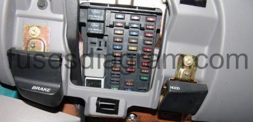
fuse box locaton.
The fuse panel is located below and to the left of the steering wheel by the brake pedal. Remove the panel cover to access the fuses. To remove a fuse use the fuse puller tool provided on the fuse panel cover.

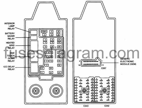
Identifying fuse panel.
Fuse box diagram.

fuse box panel legend.
| Fuse Position | Amps | Circuits Protected |
| 1 | 25 | Radio, Subwoofer Amplifier |
| 2 | 5 | Instrument Cluster. Overhead Trip Computer (OTC; Module, Powertrain Contra! Module (PCM), Electronic Automatic Temperature Control (EATC). Clock, Navigation |
| 3 | 20 | Cigar Lighter, Data Link Connector !DLC) |
| 4 | 7.5 | Remote Anti-Theft Personality (RAP) Module, Power Mirror Switch. Memory System |
| 5 | 15 | Digital Transmission Range (DTR) Sensor, Speed Control Servo, Function Selector Switch, Blend Door Actuator, Electronic Variable Orifice (EVO) Module, Daytime Running Lamps (DRL) Relay Block |
| 6 | 5 | Shift Lock Actuator, Generic Electronic Module (GEM), Air Suspension/EVO Steering Module, Compass Sensor, Steering Wheel Potation Sensor, Heated Grid Relay, Overhead Trip Computer (OTC) Module, Instrument Cluster, Reverse Sensing System |
| 7 | 5 | Auxiliary A/C Relay, Console Blower Relay |
| a | 5 | Radio, Remote Anti-Theft Personality (RAP) Module, Clock, Cellular Phone Support Electronics, Navigation |
| 9 | – | NOT USED |
| 10 | – | NOT USED |
| 11 | 30 | Washer Pump Relay, Wiper Run/Park Relay, Wiper HI/LO Relay, Windshield Wiper Motor, Rear Washer Pump Relay |
| 12 | 15 | Air Suspension Service Switch |
| 13 | 20 | Brake Pedal Position (BPP) Switch, Brake Pressure Switch, Flasher Relay |
| 14 | 15 | Battery Saver Relay, Interior Lamp Relay |
| 15 | 5 | Generic Electronic Module (GEM). Brake Pedal Position (BPP) Switch |
| 16 | 20 | Instrument Cluster, High Beam Headlamps (Power supplied through Multifunction Switch) |
| 17 | 10 | Heated Backlit Switch, Left Extenor Rear View Mirror. Right Exterior Rear View Mirror |
| 18 | 5 | Main Light Switch, Instrument Illumination (Power supplied through Main Light Switch), Clock, Navigation |
| 19 | – | NOT USED |
| 20 | 5 | Air Suspension/EVO Steering Module, Generic Electronic Module (GEM), Driver Seat Module, Radio |
| 21 | 15 | Digital Transmission Range (DTR) Sensor, Central Junction Box (fuse 20) |
| 22 | 10 | Air Bag Diagnostic Monitor, Function Selector Switch, Blower Relay, Electronic Automatic Temperature Control (EATC), Central Junction Box (Fuse 7) |
| 23 | 10 | Trailer Tow Battery Charge Relay, Auxiliary A/C Blend Actuator Electronic Day/Night Mirror, Rear Integrated Control Panel, Heated Seats, Auxiliary A/C Mode Actuator, Auxiliary A/C Control Module, Flasher Relay. Torque On Demand TOD) Relay, 4 Wheel Anti-Lock Brake System (4WABS) Module |
| 24 | – | NOT USED |
| 25 | – | NOT USED |
| 26 | 10 | Right Headlamp (Power Supplied Through Multifunction Switch) |
| 27 | 5 | Main Light Switch, Fog Lamp Relay |
| 28 | 10 | Left Headlamp (Power Supplied Through Multifunction Switch) |
| 29 | 5 | Autolamp Module, Transmission Control Switch (TCSV |
| 30 | 30 | Radio Noise Capacitor, Ignition Coil, PCM Power Diode, Coil On Plugs, Anti-Theft Transceiver Module, instrument Cluster |
| 31 | 10 | Rear Integrated Control Panel (Я1СР) (To Audio), CD Player, Cellular Phone |
Power distribution box Ford Expedition.
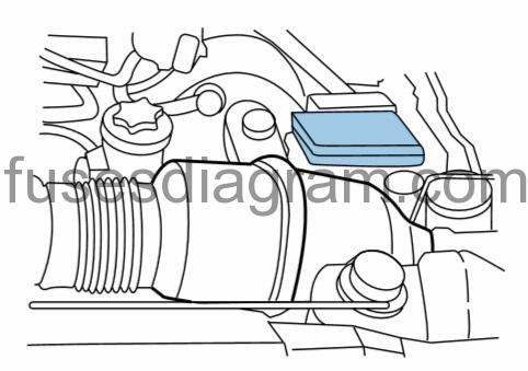
fuse box locaton.
The power distribution box is located in the engine compartment. The power distribution box contains high-current fuses that protect your vehicle's main electrical systems from overloads.

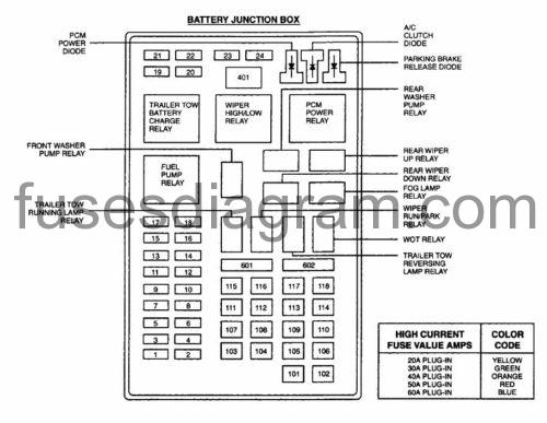
Identifying power distribution box (fuses and releys).
Fuse box diagram

| Mini Fuses | Amps | Circuits Protected |
| t | 20 | Auxiliary Power Socket |
| 2 | 30 | PCM Power Relay |
| 3 | 30 | Main Light Switch, Headlamp Relay, Multifunction Switch |
| 4 | 20 | Console Auxiliary Power Socket |
| 5 | 20 | Trailer Tow Running Lamp Relay, Trailer Tow Reversing Lamp Relay |
| 6 | 15 | Main Light Switch, Park Lamp Relay |
| 7 | 20 | Horn Relay |
| В | 30 | Lock Relays |
| 9 | 15 | Daytime Running Lamps (DRL) Resistor, Fog Lamp Relay |
| 10 | 20 | Fuel Pump Relay |
| 11 | 20 | Charging System |
| 12 | 10 | Rear Wipers Up and Down |
| 13 | 15 | WOT Relay |
| 14 | – | NOT USED |
| 15 | 10 | Right Running Board Lamp. Left Running Board Lamp |
| 16 | – | NOT USED |
| 17 | 10 | Radio, Vent Windows |
| 18 | 15 | Fuel injectors, PCM |
| 19 | 10 | Trailer/Camper Adapter, Right Stop/Tum |
| 20 | 10 | Trailer/Camper Adapter, Lett Stop/Tum |
| 21 | – | NOT USED |
| 22 | – | NOT USED |
| 23 | 15 | Heated Oxygen Sensors. Transmission |
| 24 | – | NOT USED |
| Maxi Fuses | Amps | Circuits Protected |
| 101 | 30 | Trailer Tow Battery Charge Relay |
| 102 | 50 | (4WABS) Module |
| 103 | 50 | Central Junction Box |
| 104 | 30 | Transfer Case Shift Relays, Torque On Demano (TOO) Relay |
| 105 | 40 | Blower Relay |
| 106 | – | NOT USED |
| 107 | 30 | Passenger Power Seat Control Switch, Passenger Power Lumbar Switch |
| 108 | 30 | Trailer Electronic Brake Control |
| 109 | 50 | Air Suspension Compressor Relay |
| 110 | 30 | Climate Seat Control Module, heated Seat Modules |
| 111 | 40 | Ignition Switch |
| 112 | 30 | Power Seat Control Switch, Driver Power Lumbar Switch |
| 113 | 40 | Ignition Switch |
| 114 | 30 | Auxiliary A/C Relay |
| 115 | – | NOT USED |
| 116 | 40 | Heated Grid Relay |
| 117 | – | NOT USED |
| ПВ | – | NOT USED |
| 601 c.b. | 30 | Acc Delay Relay |
| 602 C-b. | – | NOT USED |
Source: https://fusesdiagram.com/ford/fuse-box-diagram-ford-expedition.html
Posted by: allenthiscedoad.blogspot.com
Posting Komentar